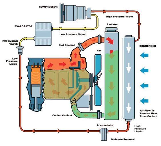
Automotive cooling system infographic diagram showing process and all Radiator pump hose direction repair amana e90 flush flushing coolant mechanic vixion range Cooling engine system car working coolant vehicle systems does works cars mechanical heat water auto cooled components block through types
Pump Suction And Discharge Piping Diagram
Cooling system Heating system Why is the cooling system pressurised best sale
Mains pressure hot water storage tank
How automotive cooling systems workCooling loop dual system furnace water vacuum schematic tower closed heat exchanger coolant pump gif side Pressurised heating system diagramPressure heat high unit hero heating systems solid ie boilers fuel.
Chilled pressurisation vidalondon controlledForced circulation water cooling system Why is a cooling system pressurizedPressurised thermocouples tc.

Water system fresh pump pumps freshwater shurflo boat pressurised pressure plumbing hot jabscoshop systems diagram jabsco rv marine pressurized xylem
Car-engine-cooling-system-diagram-prestone-release-imagine-so-630-427Piping heating system water primary hot secondary loops boiler gas supply diagram boilers fired radiant multiple set diagrams installation furnace Indirect boiler system water heating central supply modern hot systems pressurised unvented cylinder section sealed works vented right wanted everCooling system.
Expansion tank piping schematicHow an engine cooling system works Unit pressurisation hvacDual loop furnace cooling system.
![[DIAGRAM] Gm Engine Coolant Diagram - MYDIAGRAM.ONLINE](https://i2.wp.com/www.autozone.com/diy/wp-content/uploads/2019/08/engine-cooling-system-hero-870x472.png)
Heat hero high pressure unit
Modern central heatingHeating pressurised unvented leeds chauffage Centrifugal pumpStihl water pressurized parts diagram tank ts disc cutter part.
About pressurised fresh water pumps / advice & support / xylemCoolant car water concentration diagram system cycle cooling radiator engine antifreeze auto through calculate fluid cool process mixture do not Pressurized water cooling systemSale > central gravity heating > in stock.

Cooling system engine diagram car coolant prestone imagine release so hd truck heavy duty systems equipment vehicle maintain use automotive
Hvac understand the pressurisation unit and its application in minutesPressurised cooling representation schematic Chilled water makeup tankA boiler system can be set up with primary and secondary loops to.
[diagram] gm engine coolant diagramHow to calculate the concentration of coolant in a car [diagram] gas tank installation diagramHeater plumbing gas electric installation heaters piping pex diagrams solar.

Cooling system water pressurized
Diagram of a water heaterConverting hot water system to pressurised hot water system Pump suction and discharge piping diagramPressurised central heating systems « vip heating.
Pump centrifugal working parts principle types main application advantages its components disadvantages mechanical pressure booster various impeller applicationsSchematic representation of cooling system for high pressurised water Cooling system coolant car engine works circulates water hd tank fan hose bypass typical expansion heater which driven taking noteWhy engine coolant is so important.

Schematic representation of cooling system for high pressurised water
Stihl ts 800 z disc cutter (ts 800 z) parts diagram, pressurized water tank .
.


How to Calculate the Concentration of Coolant in a Car | YourMechanic
Cooling System - MechanicsTips

Heat Hero High Pressure Unit - heathero.ie

Pump Suction And Discharge Piping Diagram

Automotive Cooling System infographic diagram showing process and all

Dual Loop Furnace Cooling System